 English
 Español
 عربى
عربى Türk
Türk


The Purpose of Laminating a Transformer Core
Content
- 1 The Core Problem: Why Solid Metal Fails
- 2 The Solution: Lamination and Its Purpose
- 3 Material Science in Transformer Core Lamination
- 4 Lamination Configurations: Comparing Core Types
- 5 Modern Manufacturing Techniques
- 6 Practical Trade-offs and Design Decisions
- 7 Frequently Asked Questions (FAQs)
- 7.0.1 Q1: What is the main purpose of laminating a transformer core?
- 7.0.2 Q2: How does lamination reduce energy loss?
- 7.0.3 Q3: What materials are used for transformer core laminations?
- 7.0.4 Q4: Why are laminations insulated from each other?
- 7.0.5 Q5: Does lamination affect the transformer's mechanical stability?
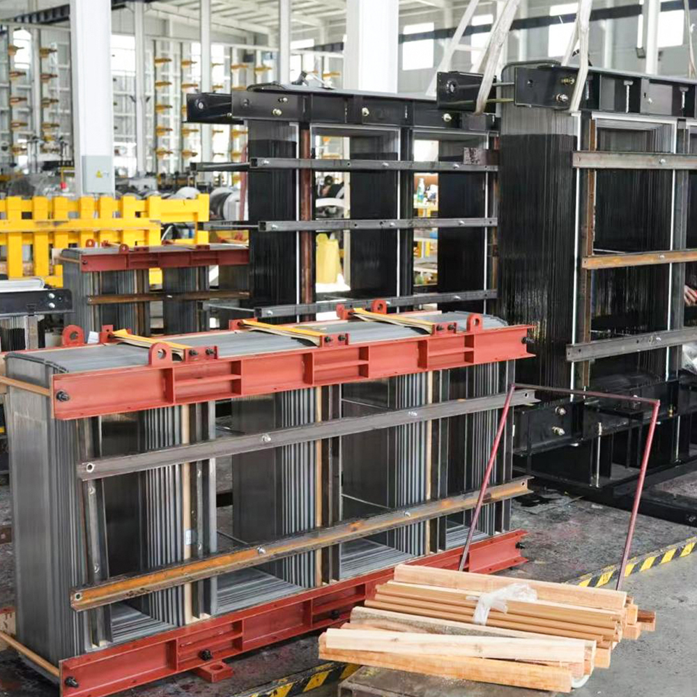
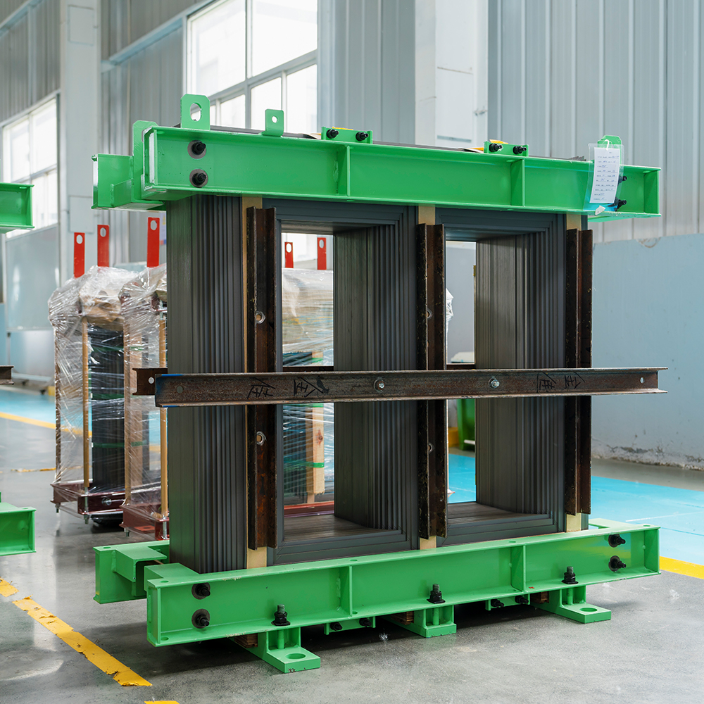
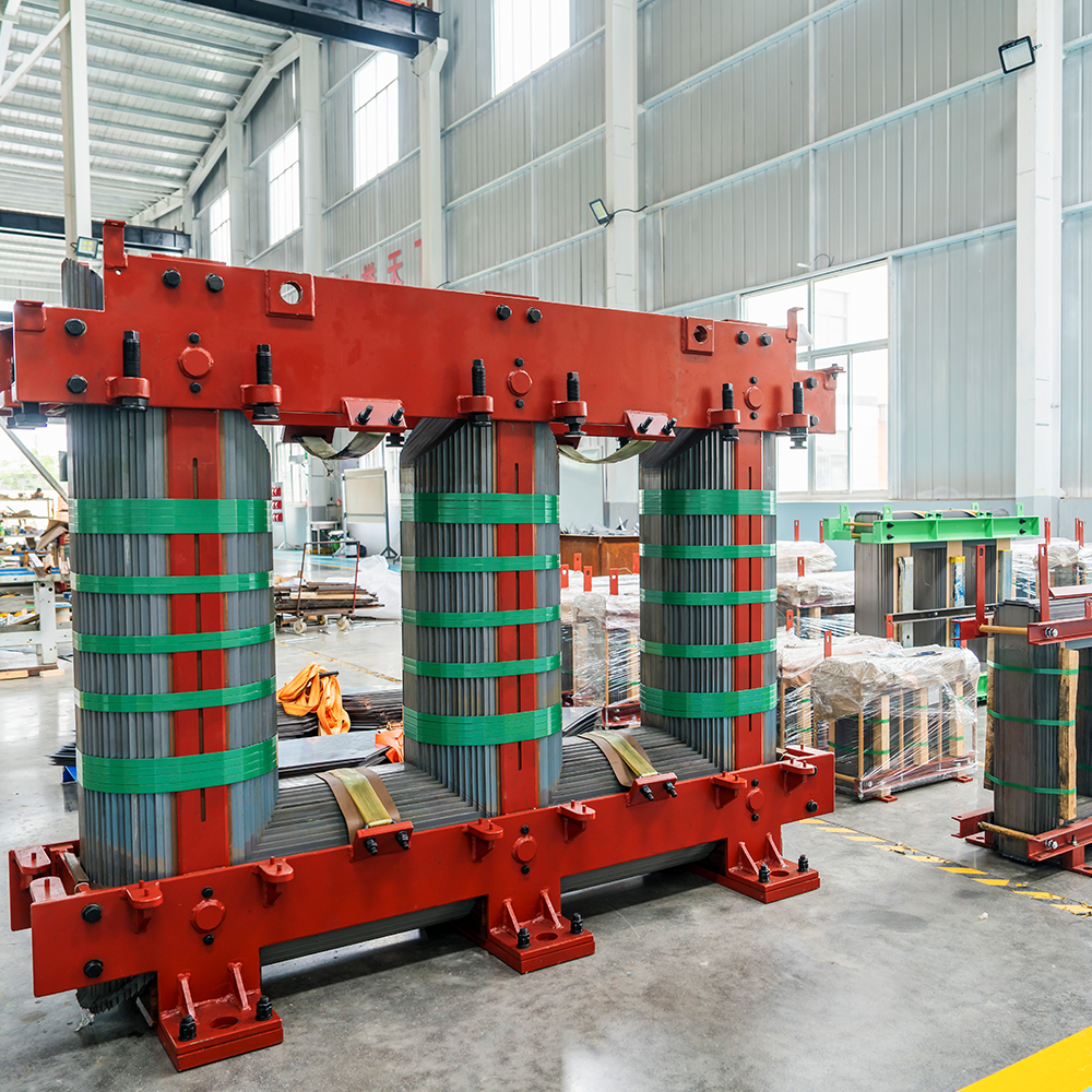
At the heart of every electrical transformer lies a component that is both simple in concept and critical in performance: the transformer cores. This magnetic circuit serves as the pathway for flux, enabling the transfer of electrical energy from one winding to another through electromagnetic induction. However, the path of magnetic flux is not without its challenges. One of the most significant engineering decisions in transformer design is the construction of this core not as a single, solid block of metal, but as a stack of thin, insulated sheets. This process, known as lamination, is fundamental to the efficiency, longevity, and practical operation of virtually all modern transformers. This article delves deeply into the technical reasons why transformer cores are laminated, exploring the physics of energy loss, material selection, and the sophisticated engineering that makes this design so effective.
The Core Problem: Why Solid Metal Fails
To understand the necessity of laminating a transformer core, we must first look at the behavior of a solid, conductive metal when subjected to a changing magnetic field. The very principle of a transformer—a changing current in the primary coil creating a changing magnetic flux in the core—is also the source of its most significant internal inefficiencies. When magnetic flux flows through a solid core, it induces a voltage within the metal itself. This voltage creates circulating currents that flow in closed loops perpendicular to the magnetic flux. These are eddy currents.
The Eddy Current Problem
Eddy currents are a direct consequence of Faraday's law of induction. In a solid steel core, these currents can be substantial, as they have a large cross-sectional area of highly conductive material to flow through. The primary issue with eddy currents is that they generate heat (I²R losses), which represents a direct loss of electrical energy. This energy does not perform useful work in the secondary circuit but instead warms the transformer. To visualize this, consider the cross-section of a solid core. The changing magnetic field over a large area induces a significant electromotive force, leading to large, swirling currents.
The magnitude of eddy current loss is proportional to the square of both the frequency of the alternating current and the thickness of the core material. This relationship is crucial: as the thickness of the conductive path increases, losses escalate dramatically. The heat generated by these losses not only wastes energy but also raises the operating temperature of the transformer. Excess heat can degrade the insulation of the windings, shorten the lifespan of the transformer, and in extreme cases, lead to catastrophic failure. Furthermore, from an economic standpoint, even a seemingly small percentage of energy loss in a single transformer becomes a significant waste of power over time, especially in large-scale power distribution networks.
The Solution: Lamination and Its Purpose
Lamination is the engineering response to the eddy current problem. Instead of using a single thick block of magnetic material, the core is constructed from many thin sheets of steel, each individually coated with an insulating layer. These sheets are then stacked and bonded together to form the complete core. The primary purpose of this design is to drastically reduce the magnitude of eddy currents.
Interrupting the Path
By slicing the core into thin laminations, the cross-sectional area available for eddy current flow is dramatically reduced. Since eddy current loss is proportional to the square of the thickness, reducing the thickness by a factor of, for example, 10, can reduce losses by a factor of 100. The thin, insulating layers between the laminations do not conduct electricity, effectively interrupting the path of the circulating currents and forcing them to be confined to the small cross-section of each individual sheet. This is the most fundamental and critical purpose of laminating a transformer core.
Other Critical Benefits of Lamination
While reducing eddy current losses is the paramount objective, the laminated construction of a transformer core offers several other significant engineering advantages.
- Reduction of Hysteresis Losses: While lamination is primarily for eddy currents, the use of thin sheets of high-grade steel also helps manage hysteresis losses. These losses arise from the energy required to continuously reorient the magnetic domains within the core material as the alternating current changes direction. Silicon steel, the preferred material for laminations, is designed with a specific grain orientation to minimize the energy required for this magnetic reversal.
- Thermal Management: The thin laminations and their insulating coatings allow for more efficient heat dissipation. Heat generated within the core can more easily travel to the surface of each lamination and be removed by the transformer's cooling system, preventing hot spots that could damage the core or surrounding insulation.
- Mechanical Stability and Noise Reduction: The stacking of laminations, often bonded together with an adhesive, creates a mechanically robust core that can withstand the immense magnetic forces present during operation. Furthermore, adhesive bonding can change the vibrational mode of the core, reducing the audible hum often associated with transformers. Some designs intentionally bond groups of six or seven laminations together, forcing them to vibrate as a single, heavier unit at a lower frequency, which reduces the overall acoustic noise generated.
Material Science in Transformer Core Lamination
The effectiveness of a laminated transformer core hinges not just on the geometry of the laminations but also on the materials from which they are made. The choice of material is a careful balance between magnetic properties, electrical resistivity, mechanical workability, and cost.
Silicon Steel: The Industry Standard
The most common material for transformer core laminations is silicon steel. It is an alloy of iron with a small percentage of silicon, typically up to 6.5%. The addition of silicon serves several crucial functions:
- Increased Electrical Resistivity: Silicon increases the electrical resistivity of the steel. This is a key advantage because it further reduces the magnitude of eddy currents, even before the core is laminated. The higher resistivity acts as a first line of defense against losses.
- Reduced Hysteresis Losses: Silicon steel exhibits favorable magnetic properties, including a narrow hysteresis loop, which translates to lower hysteresis losses during the magnetization cycle.
- Grain-Oriented vs. Non-Oriented: The performance of a transformer core is also heavily influenced by the crystalline structure of the steel. Grain-oriented silicon steel is processed in a way that aligns the magnetic domains predominantly in the rolling direction. This provides superior magnetic permeability and lower core losses when the flux is aligned with this direction. This is why it is the material of choice for power transformers, where the flux path is well-defined. Non-oriented steel, on the other hand, has a more random grain structure, providing isotropic magnetic properties. This is used in applications where the flux direction may vary or where cost is a primary concern.
Innovative Core Designs and Materials
While laminated silicon steel is the industry workhorse, other materials and configurations are also used, each with a specific set of trade-offs.
- Ferrite Cores: These are made of sintered ceramic-like materials composed of iron oxides mixed with other metallic elements. They have extremely high electrical resistivity, effectively eliminating eddy currents. This makes them ideal for high-frequency applications, such as in switch-mode power supplies, where losses in steel would be unacceptably high. However, ferrite cores have lower magnetic flux density capabilities than steel, meaning they require larger cores for the same power level.
- Amorphous and Nanocrystalline Cores: These are made from extremely thin ribbons of metal that are rapidly cooled from a molten state, resulting in a non-crystalline, or amorphous, atomic structure. This material offers very low hysteresis losses. However, it is more expensive and challenging to manufacture and may be more sensitive to mechanical stress, requiring more care in the assembly of the transformer core.
Lamination Configurations: Comparing Core Types
The geometry of the laminations themselves also affects performance. Different core shapes, such as EI, toroidal, and C-core, use laminations in different ways to optimize flux paths, minimize waste, and simplify manufacturing. The table below illustrates some of these trade-offs.
| Core Type | Lamination Shape | Key Advantages | Typical Applications |
| EI Core (Stacked) | E and I shaped sheets | Low manufacturing cost, simple assembly | General-purpose transformers, power supplies |
| Toroidal Core | Continuous strip wound in a ring | High efficiency, low leakage flux, compact | Audio transformers, precision instruments |
| C-Core (Cut Core) | Two "C" halves from a wound strip | Allows for easy coil insertion, controllable air gaps | High-power inductors, specialized transformers |
Modern Manufacturing Techniques
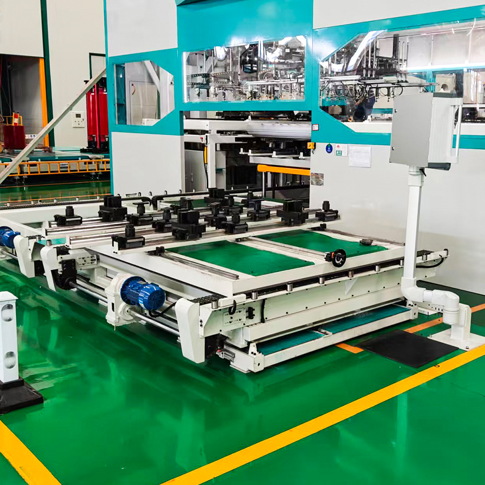
The process of creating a laminated transformer core has evolved from simple manual stacking to sophisticated, automated processes that ensure precision, efficiency, and optimal performance.
Cutting and Stamping
The journey begins with a large coil of silicon steel, which is fed into a high-speed stamping press. The press uses custom-designed dies to cut the individual laminations from the steel strip. This process is highly efficient and can produce thousands of laminations per minute. The shape of the lamination is dictated by the core's final geometry—an "E" and "I" shape for an EI core, or a continuous spiral for a toroidal core. Modern machinery allows for precise control over the cutting process, ensuring that laminations are uniform and free of defects that could impact magnetic performance.
Insulation and Stacking
After cutting, the laminations are coated with an insulating layer. This is often a thin layer of varnish or an oxide layer, but the patent literature reveals more advanced methods. For instance, a thermosetting resin composition containing an epoxy resin and inorganic particles can be applied to create an insulating and adhesive layer simultaneously. This dual-purpose coating is a significant innovation. The adhesive bonds the laminations together, enhancing mechanical stability and reducing vibration, while the insulating properties are maintained by the inorganic particles, which prevent metal-to-metal contact between the sheets.
Bonding
Early methods of bonding laminations involved mechanically clamping the finished stack. While still used, this is being increasingly replaced by adhesive bonding. Some modern methods involve applying a pattern of thin adhesive beads onto the steel surface before stacking. This approach offers several advantages: it reduces the space factor (the percentage of core volume occupied by steel), minimizing a slight increase in core loss that can occur with full-surface coatings. Moreover, the adhesive layer can be designed to absorb mechanical vibrations, reducing the transformer's audible noise. In some advanced embodiments, groups of six or seven laminations are bonded together as a single sub-assembly, which is then handled as a unit, simplifying the final stacking process.
Practical Trade-offs and Design Decisions
While lamination provides overwhelming benefits, it is not without its trade-offs. A balanced design considers these factors to optimize the overall transformer core.
- Space Factor: Laminations and their insulating coatings do not occupy 100% of the core's physical volume. The space factor, or fill factor, represents the percentage of the core cross-section that is actually magnetic steel. A lower space factor means a larger core is needed to achieve the same magnetic performance, which increases the transformer's size and weight. Adhesive bonding methods that use thin, precise coatings help to maintain a high space factor, sometimes limiting the reduction to less than 0.5%.
- Cost Considerations: The process of cutting, coating, and stacking laminations is more expensive than casting or forging a solid core. However, the operational savings from reduced energy losses over a transformer's lifetime far outweigh the higher initial manufacturing cost. Furthermore, the use of low-cost tooling and efficient manufacturing methods, such as the C-I core design which combines a cut core with a laminated "I" bar, represents a lower-cost approach that still offers the performance benefits of laminations.
- Mechanical Integrity: The core must withstand the powerful electromagnetic forces that are generated during operation. These forces cause the core to expand and contract, and without proper bonding, the laminations could slip or vibrate excessively. Adhesives and clamping mechanisms are designed to secure the stack, ensuring it remains a solid, single unit that can handle these mechanical stresses.
Frequently Asked Questions (FAQs)
Q1: What is the main purpose of laminating a transformer core?
The primary purpose is to reduce eddy current losses. By dividing the core into thin, insulated sheets, the path for circulating currents is disrupted, dramatically reducing the energy wasted as heat.
Q2: How does lamination reduce energy loss?
Lamination reduces energy loss by confining eddy currents to the small cross-sectional area of each individual sheet. Since eddy current loss is proportional to the square of the material's thickness, using thin laminations drastically reduces these losses.
Q3: What materials are used for transformer core laminations?
The most common material is silicon steel, which is chosen for its high magnetic permeability and increased electrical resistivity. Other materials include ferrite, used for high-frequency applications, and amorphous or nanocrystalline alloys, used for applications where ultra-low losses are required.
Q4: Why are laminations insulated from each other?
The insulating layer between laminations is essential to prevent the flow of eddy currents from one lamination to another. If the sheets were in direct electrical contact, they would essentially function as a single, larger conductor, restoring the path for large eddy currents and defeating the purpose of lamination.
Q5: Does lamination affect the transformer's mechanical stability?
Yes. While the individual sheets are thin, modern manufacturing processes use adhesives or clamping mechanisms to bond the laminations into a solid, mechanically robust core. This prevents vibration, reduces audible noise, and ensures the core can withstand the intense magnetic forces present during operation.
-
Mobile
+86-18351152766
-
E-mail
479279940@qq.com
-
Address
No.3 Park, Jiangcun Village, Liangxu Town, Jiangyan District, Taizhou City, Jiangsu Province, China


Copyright © Jiangsu Jingtianxia Electric Technology Co., Ltd. Rights Reserved.Specializing In Transformer Core Manufacturing
