English


Applications
Feedback
Buyer's Responsibilities
- Supply and connect the power cable to the equipment electrical cabinet per public utility conditions; connect the required grounding cable to the designated connection point on the equipment.
- Construction of equipment foundations, pipelines, embedded parts, and grounding systems.
- Lifting equipment (crane, forklift, etc.) required for unloading, positioning, and installation/commissioning of equipment at the buyer's site.
- Water, compressed air (including 2 m³ air receiver tank), electricity, and auxiliary materials for equipment commissioning.
- Materials required for trial operation during commissioning.
Delivery, Acceptance & Inspection
- Inspection standards: this Technical Agreement and the manufacturer's applicable national standards.
- Acceptance and inspection shall be carried out by both parties at the supplier's production site in accordance with the Technical Agreement; equipment is shipped after passing inspection.
- Full performance testing shall be conducted at the end user's site; both parties shall perform item-by-item acceptance per the Contract and Technical Agreement; an Acceptance Report shall be signed by both parties upon passing.
Equipment Composition
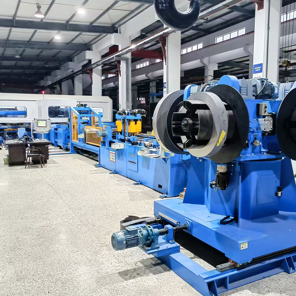
| Complete Equipment Composition | |||
| No. | Component | Qty. | Remarks |
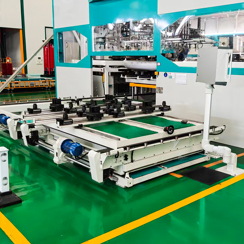
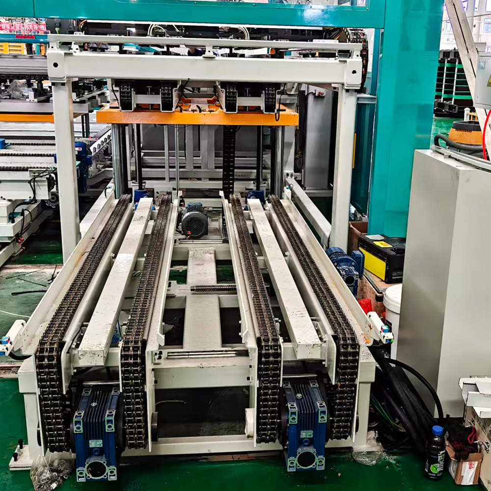
| 1 | Yoke Lamination Column Pre-storage Cart | 1 set | |
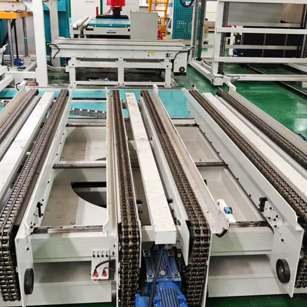
| 2 | Yoke Lamination Column Transfer Conveyor Line | 1 set | |
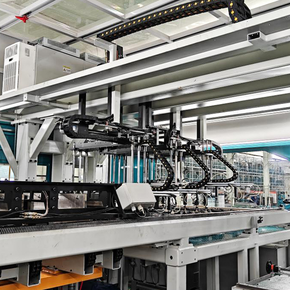
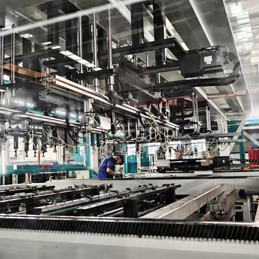
| 3 | Yoke Lamination Grab & Lift Mechanism | 1 set | |
| 4 | Yoke Lamination Gripping Mechanism | 1 set | |
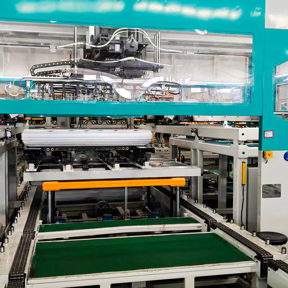
| 5 | Yoke Lamination Material Transport & Positioning Track | 1 set | |
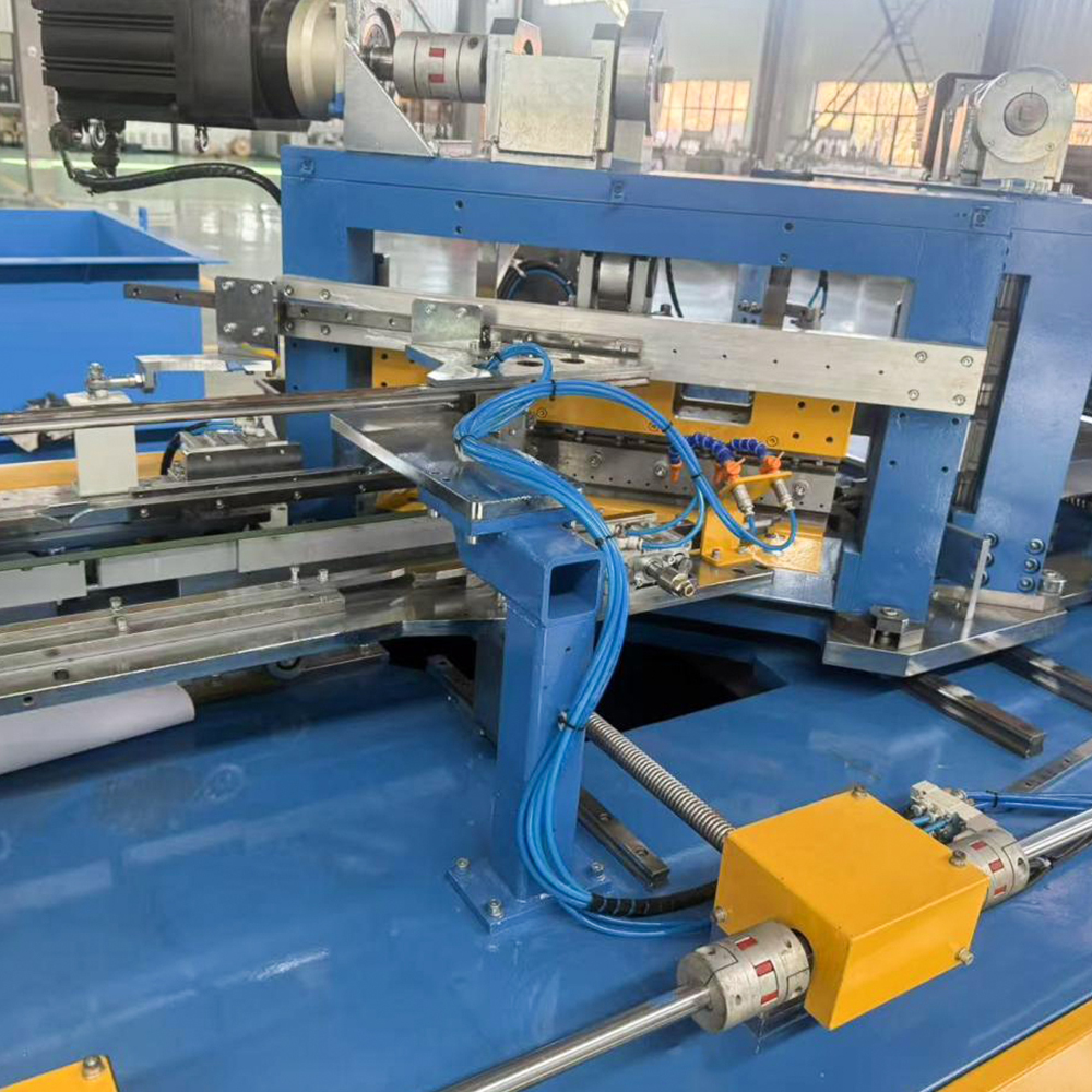
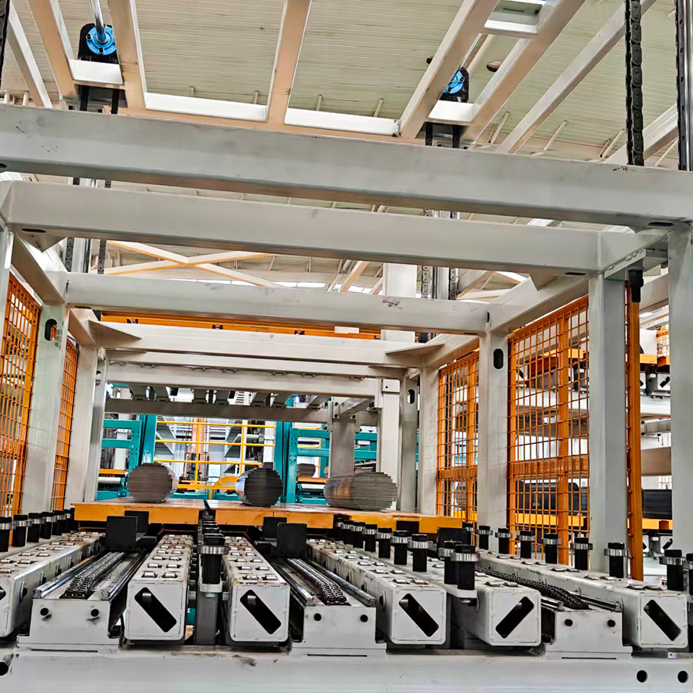
| 6 | Yoke, Center Limb & Side Lamination Stacking Mechanism | 1 set | |
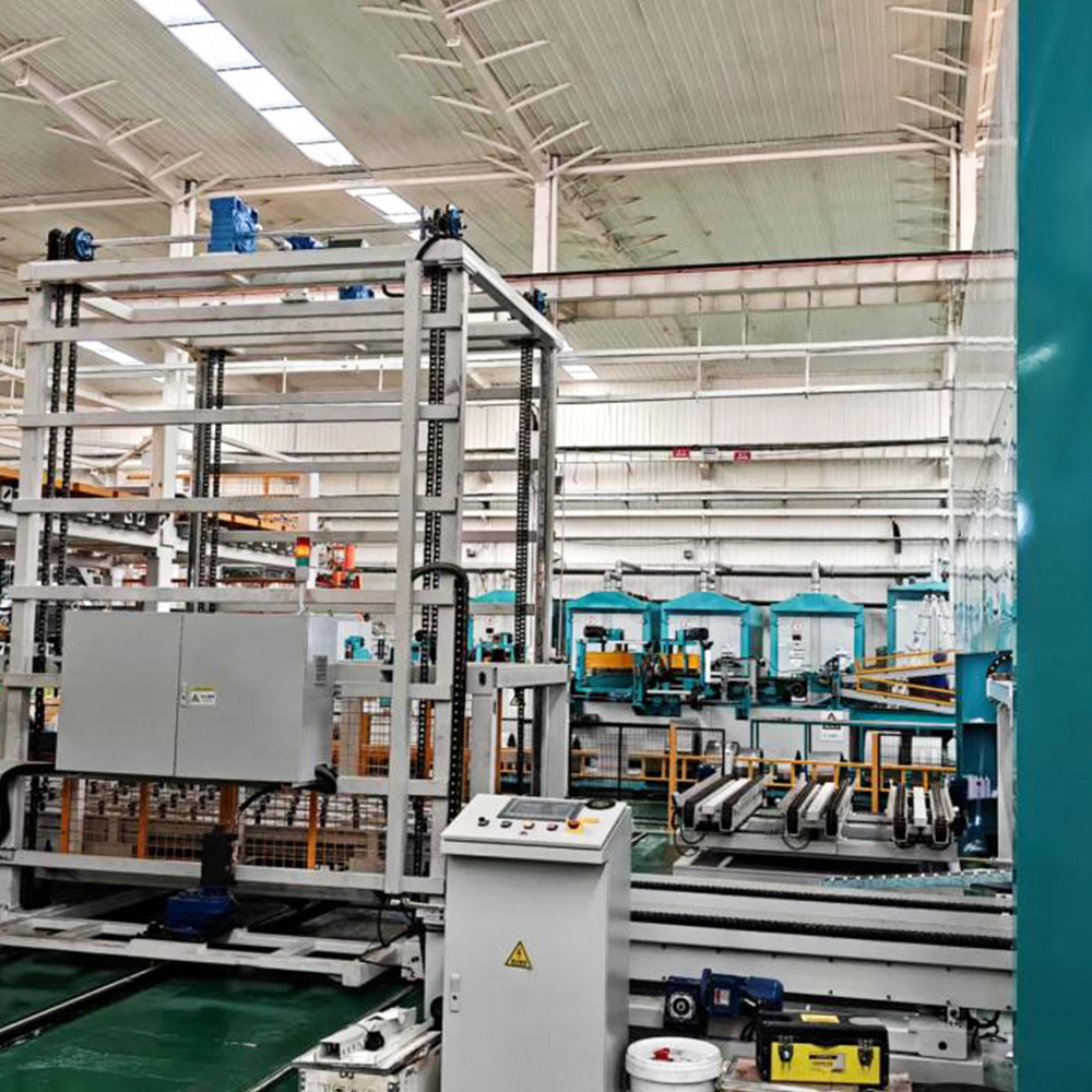
| 7 | Finished Product Stacking Elevator | 1 set | |
| 8 | Center Limb & Side Lamination Transport & Positioning Guide Rail | 1 set | |
| 9 | Center Limb & Side Lamination Gripping Mechanism | 1 set | |
| 10 | Center Limb & Side Lamination Grab & Lift Mechanism | 1 set | |
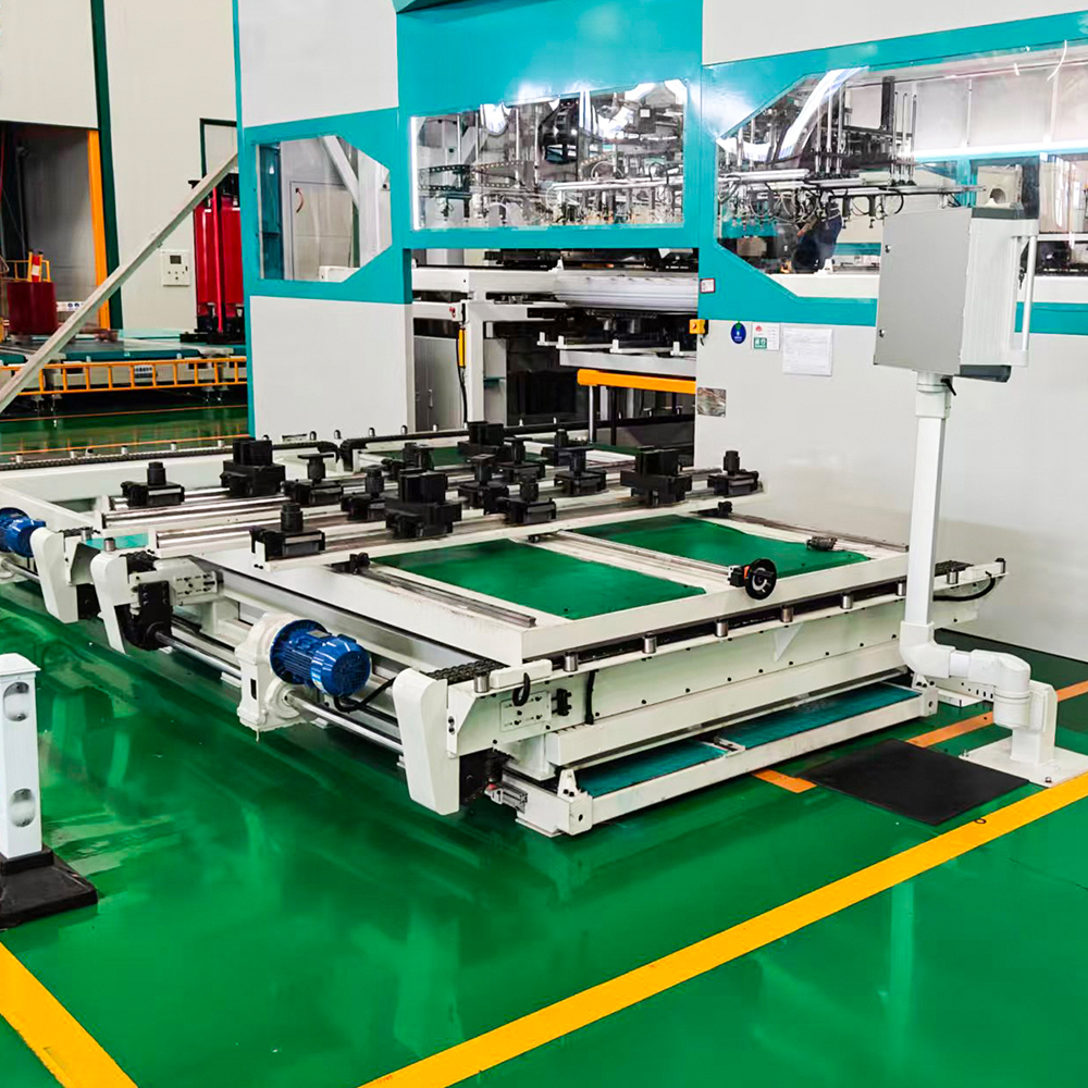
| 11 | Center Limb & Side Lamination Column Transfer Cart | 1 set | |
| 12 | Center Limb & Side Lamination Rotation Cart with Pre-storage | 1 set | |
| 13 | Finished Product Transport Line & Finished Product Clamping Positioning Platform | 1 set | |
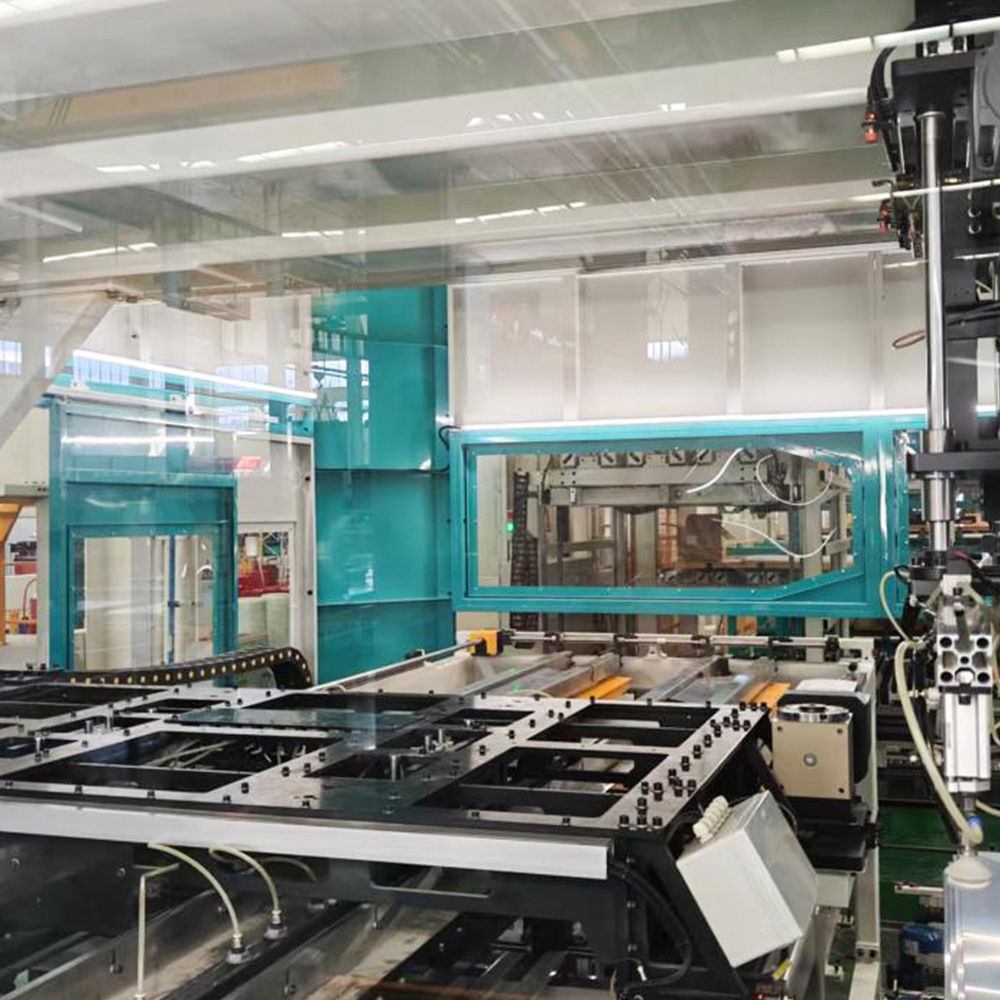
| 14 | Safety Guards | 1 set | |
| 15 | Electrical Control Cabinet | 1 set | Includes system controller, servo drives, and frequency inverter |
Main Technical Parameters
| No. | Performance Parameter | LXD-260-2 | ||
| 1 | Lamination Specifications | Width | 40–260 mm | |
| Thickness | 0.18–0.3 mm | |||
| Side Limb Length | 450 mm (centerline length) – 1700 mm (tip-to-tip length) | |||
| Yoke Length | 450 mm (centerline length) – 1700 mm (tip-to-tip length) | |||
| Center Limb | 450–1440 mm (tip-to-tip length) | |||
| Max Core (L×W×H) | 1700×1700×400 mm | |||
| 2 | Required Lamination Accuracy (supplied by buyer) | S-Value (Bow) | Single-sided error within total length ≤0.1 mm | |
| Waviness | Height error within total length ≤2 mm | |||
| Burr | ≤0.02 mm | |||
| Width | ≤±0.1 mm | |||
| Length | ≤±0.2 mm | |||
| Center Limb Angle Deviation (after left/right flip) | ≤0.1 mm | |||
| Length Consistency of Yoke, Side & Center Limb | ≤0.1 mm | |||
| 45° Angle Accuracy of Side, Yoke & Center Limb | ≤±0.025° | |||
| V-Notch & 45° Angle Overlap (same yoke flipped) | ≤0.1 mm | |||
| 3 | Stacking Accuracy | Same-grade Length Direction | ≤±0.5 mm (excluding supplied sheet accuracy error) | |
| Same-grade Width Direction | ≤±0.5 mm (excluding supplied sheet accuracy error) | |||
| Same-grade Thickness Error (stacked by sheet count) | ≤1 mm (excluding supplied sheet thickness error) | |||
| Note: | Core accuracy is simultaneously affected by sheet cutting accuracy and stacking accuracy. Manual reshaping after stacking is required to achieve higher precision. If the shutdown for reshaping due to the buyer's higher precision requirements reduces equipment productivity in normal production, responsibility lies with the buyer and is unrelated to the supplier's equipment. | |||
| 5 | Column Material Alignment Requirements | Sheet Supply and Loading | 1. Sheets are cut into columns by the transverse shearing line or manually stacked in columns according to the core drawing column structure and quantity (each grade count must be exact — excess or missing sheets will affect stacking efficiency and require manual intervention). 2. Both machine-formed and manually stacked columns must meet the column alignment requirements in this specification. 3. If the buyer's column alignment does not meet the technical parameters, or if columns contain extra, wrong, or missing sheets, causing frequent equipment stoppages affecting efficiency, the buyer is responsible for resolving the column supply issue. | |
| Column Height | ≤400 mm | |||
| 5-Limb Core Column Height Consistency | ≤1 mm | |||
| Same-grade Width Direction Misalignment | ≤5 mm | |||
| Same-grade Length Direction Misalignment | ≤5 mm | |||
| Same-grade Width Centerline Deviation on Material Slot | ≤5 mm | |||
| Column-to-Plate Width Centerline Deviation | ≤5 mm | |||
| Single-column Width Direction Misalignment | ≤5 mm | |||
| Single-column Length Direction Misalignment | ≤5 mm | |||
| Single-column 45° Bevel Side Misalignment | ≤5 mm | |||
| Single-column Center Limb Tip Misalignment | ≤5 mm | |||
| Single-column Position on Material Plate | Length-direction center position deviation ≤20 mm; End fixed position deviation ≤20 mm | |||
| 6 | Stacking Cycle Time | Approx. 6 s | 1 stroke (5 sheets/stroke); approx. 10 strokes/min; ~100 sheets/min (2-stack type) Acceptance standard core: Width 80–140 mm; Max length 850 mm (tip-to-tip); Thickness 280 mm | |
| 7 | Air Supply | Pressure | ≥0.6 MPa | |
| Total Air Consumption (energy-saving vacuum generator; low consumption; reduces compressed air costs) | ≤0.6 m³/min | |||
| 8 | Equipment Noise | ≤70 dB | ||
| 9 | Equipment Color | Factory standard: Main color: Light Grey 7035, Sky Blue 5015; Moving parts: Signal Yellow 1003. Custom colors available upon request. | ||
| 10 | Working Voltage | Voltage Fluctuation | 380 V ±10% | |
| Frequency | 50 Hz ±2% | |||
| 11 | Installed Capacity | 90 kW | ||
Main Components & Brands
| No. | Item | Brand |
| 1 | Control System & Touch Screen | Siemens |
| 2 | Servo Drive System | Siemens / Inovance / Hechuan / Weichuang |
| 3 | Frequency Inverter | Inovance or equivalent |
| 4 | Electrical Components | Schneider low-voltage switches; Panasonic relays or equivalent |
| 5 | Push Buttons | Eaton (Moeller) or equivalent |
| 6 | Solenoid Valves | SMC (Japan) or equivalent |
| 7 | Cylinders & Regulating Valves | SMC (Japan) or equivalent |
| 8 | Vacuum System & Suction Cups | SMC (Japan) or equivalent |
| 9 | Linear Guide Rails | WON (Korea) / Yintai / Jiding or equivalent |
| 10 | Ball Screws | NanGongYi (ground screws) / Jinqiu or equivalent |
| 11 | Racks & Gears | Atlanta (Germany) / APEX or equivalent |
| 12 | Variable-frequency Motors | Siemens (Bode) / Jiegong / Yinda or equivalent |
Technical Documentation
| No. | Document Name | Quantity |
| 1 | Equipment Parts List | 2 copies |
| 2 | Certificate of Conformity | 1 copy |
| 3 | Electrical Schematic Diagram | 2 printed copies + 1 electronic file |
| 4 | Electrical Wiring Diagram | 2 printed copies + 1 electronic file |
| 5 | Electrical Component Manuals | 1 copy each |
| 6 | Equipment Operation Manual (including operating procedures, maintenance & service norms) | 2 printed copies + 1 electronic file |
| 7 | Installation Floor Plan | 1 printed copy + 1 electronic file |
| 8 | Equipment Foundation Drawing | 1 printed copy + 1 electronic file |
Installation, Commissioning, Training, After-Sales Service & Warranty
| Installation, Commissioning & Training | The supplier's engineers will provide free on-site training on operation, maintenance, upkeep, and process guidance. | Time required: Installation and commissioning are generally completed within 2 weeks. Training duration is determined by the buyer's operators' proficiency and the buyer's requirements. |
| After-Sales Service | If equipment problems arise, the supplier dispatches personnel for repair and provides basic troubleshooting and daily maintenance guidance to the buyer's mechanical and electrical maintenance staff. | |
| Daily Response Time | Response within 24 hours. On-site arrival: same day within the supplier's province; next day for other provinces. | |
| Holiday Response Time | Response within 24 hours. On-site arrival during holidays if the buyer has on-duty personnel. | |
| Note: | 1. For faults requiring on-site service, arrival is generally within 24 hours; phone resolution is preferred where possible. 2. The supplier provides lifetime service; discounted spare parts, components, and technical support continue after the warranty period. 3. If the buyer defaults on payment after equipment acceptance, the supplier makes no warranty commitment. | |
| Warranty Period | 12 months from the date of final acceptance. During the warranty period, if a fault arises due to equipment quality issues or correct operation per the supplier's procedures, the supplier provides free parts and repair at no cost to the buyer. If a fault arises due to the buyer's failure to follow operating procedures or overloading, the supplier promptly resolves the fault and charges only the component cost. | |
More recommendations