 English
 Español
 عربى
 Türk



What Causes Hotspots in Large Transformer Cores? Thermal Breakdown Prevention
Content
- 1 What Are Hotspots in Large Transformer Cores?
- 2 Core Overexcitation and Voltage-Related Causes
- 3 Interlaminar Insulation Breakdown and Core Stacking Quality
- 4 Core Grounding Faults and Circulating Currents
- 5 Harmonic Loading and DC Bias
- 6 Cooling System Limitations and Thermal Concentration
- 7 Preventing Thermal Breakdown Through Manufacturing Quality
- 8 Operation and Maintenance Practices to Prevent Thermal Breakdown
- 9 Frequently Asked Questions
- 10 Conclusion
Large power transformer cores must simultaneously carry magnetic flux, withstand mechanical clamping forces, and reject internally generated heat. When heat becomes trapped in a local region, a hotspot develops. If the condition is ignored, insulation degrades faster, combustible gases accumulate, and thermal breakdown eventually follows. For engineers and asset managers, understanding what causes hotspots in large transformer cores is essential for preventing unplanned failures and extending transformer service life.
Why it matters: A hotspot is more than a temperature reading. It is an early warning that the core is already on a path toward insulation aging, gas generation, and eventual thermal failure.
What Are Hotspots in Large Transformer Cores?
A hotspot is a local temperature zone that is considerably higher than the average temperature of the core or winding. In transformer cores, hotspots typically appear where magnetic flux density is concentrated or where heat dissipation is least efficient. The heat originates from iron losses: hysteresis loss, caused by repeated magnetization of the silicon steel, and eddy-current loss, which rises with the square of flux density and frequency.
Large transformer cores are particularly vulnerable for two physical reasons. First, their large cross-sections concentrate more flux, which increases the local volumetric loss density. Second, the relatively small surface-area-to-volume ratio makes it harder for internally generated heat to reach the oil or air cooling path. A modest rise in core loss can therefore produce a distinct hotspot in the center of a limb or yoke.
If a hotspot persists, the consequences become severe. For every 6 to 10 degrees Celsius above the rated temperature limit, the thermal aging rate of cellulose insulation roughly doubles. Over time, the winding paper loses mechanical strength, the dielectric margin shrinks, and dissolved gases such as hydrogen, methane, and ethylene appear in the insulating oil. In extreme cases, the core steel itself can be damaged, leading to costly repair or complete transformer failure.
| Source | Heat Generation Mechanism | Typical Location |
|---|---|---|
| Core overexcitation | Flux density increases, raising hysteresis and eddy-current loss | Limbs, yokes, and clamping structure |
| Interlaminar insulation failure | Circulating currents flow between adjacent laminations | Core surfaces near bolt holes or cut edges |
| Multipoint grounding | Ground-loop currents circulate through core and frame | Core bottom, support structure, tie plates |
| Harmonic current loading | High-frequency eddy-current loss grows with frequency squared | Core surface and structural steel plates |
Core Overexcitation and Voltage-Related Causes
Overexcitation is one of the most common causes of core hotspots. It occurs when the ratio of voltage to frequency exceeds the design value, usually stated as the V/Hz limit. Typical triggers include sustained system overvoltage, low-frequency operation during generator startup, load rejection, and incorrect tap positions. When the core enters saturation, excess flux is forced into stray paths through the tank, clamping frames, and other structural parts, creating localized heating in areas not designed to carry high flux.
Prevention starts with accurate voltage regulation and correct tap changer settings. Most large transformers are equipped with V/Hz protection relays that alarm or trip when the ratio approaches the manufacturer's limit. Operators should also avoid running the transformer above its rated voltage for extended periods, especially at light load, because excitation current and core loss both increase sharply once saturation begins.
Interlaminar Insulation Breakdown and Core Stacking Quality
Transformer cores are built from thin electrical-steel laminations, each coated with an insulating layer that restricts eddy currents to individual sheets. If this interlaminar insulation is damaged, eddy currents can circulate across the lamination stack, generating intense localized heating. The damage is often caused by burrs left on cut edges, scratches introduced during handling, or excessive clamping pressure that fractures the coating.
The quality of core stacking is equally important. When laminations are assembled with inconsistent pressure, misaligned joints, or gaps, the magnetic circuit becomes nonuniform. The resulting flux distortion increases local loss and creates predictable hotspots. Manual stacking is inherently variable, which is why many core manufacturers now use automated stacking lines that apply even pressure, maintain precise alignment, and minimize surface contact damage.
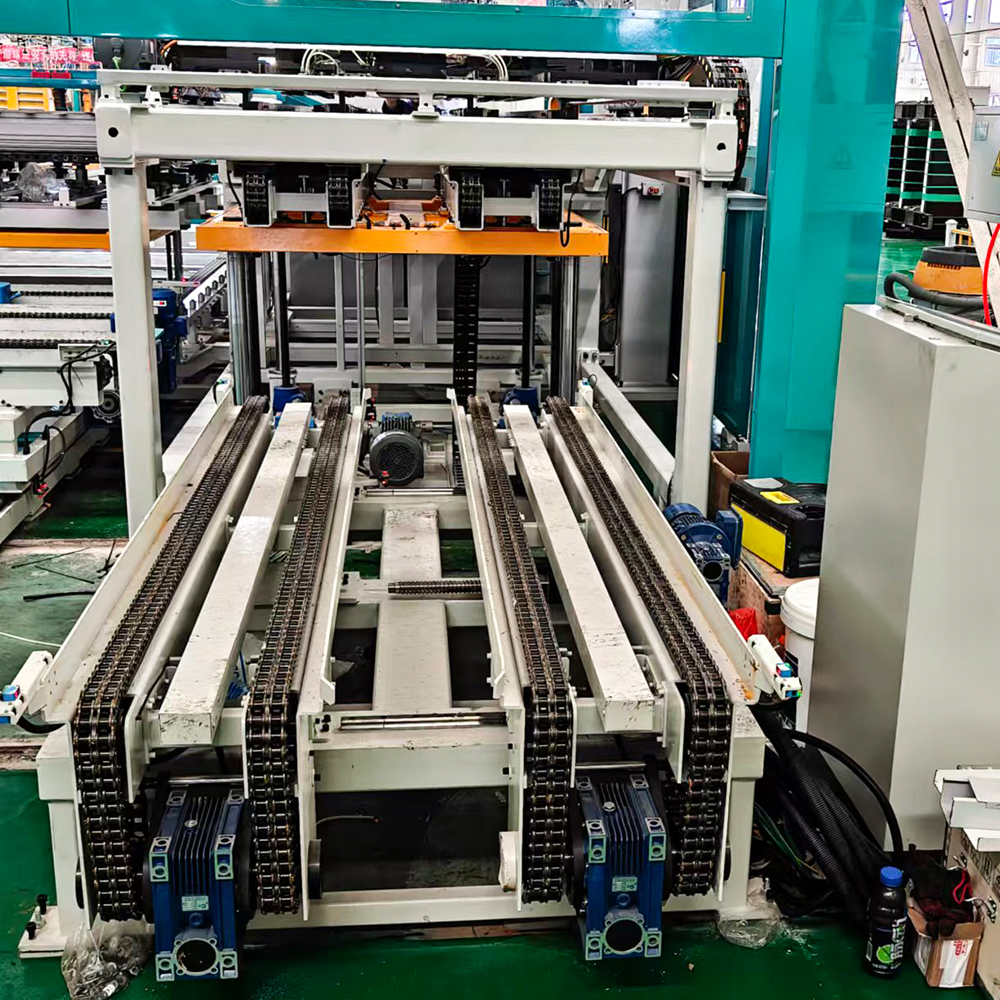
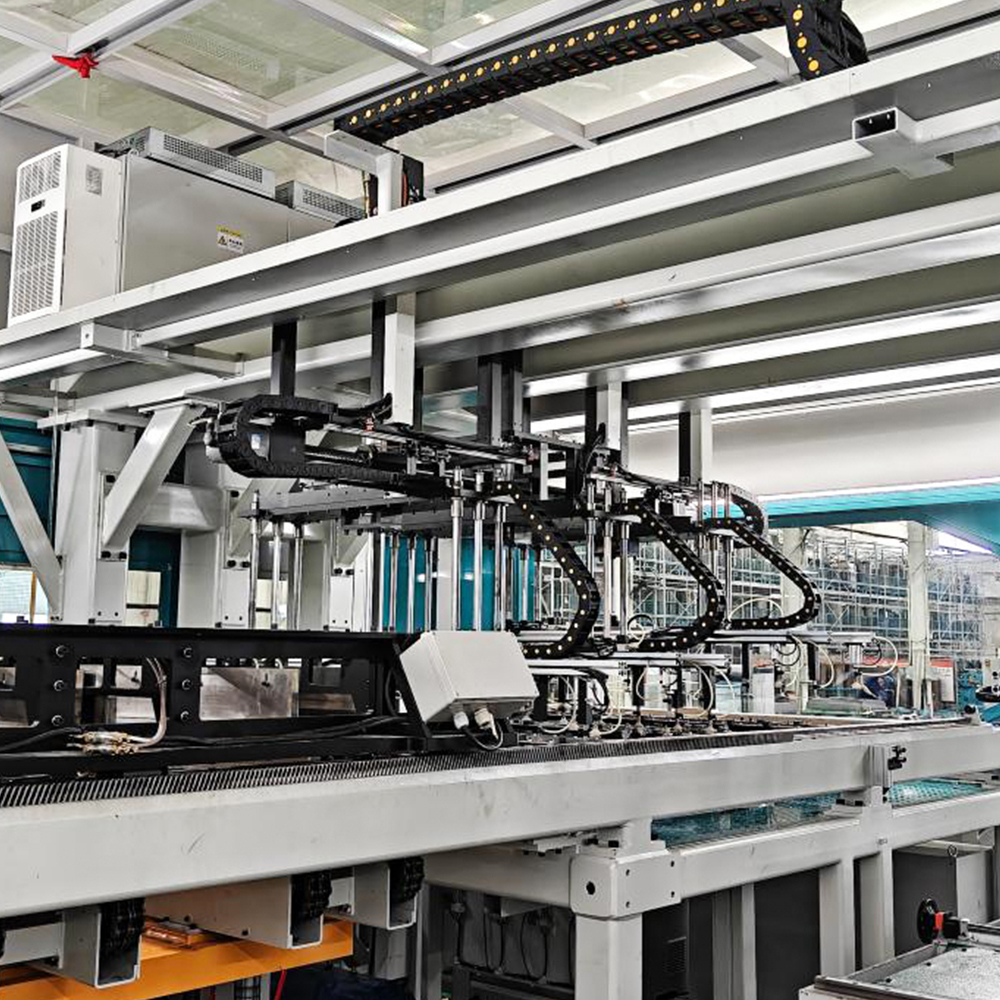 ZXD-440 Automatic In-line Transformer Core Stacking Production LineThis automated system integrates with the shearing line to stack laminations simultaneously, eliminating manual handling. Its even pressure and alignment help reduce core hotspots caused by inconsistent stacking.View Product →
Automated cut-to-length processing also helps. Clean, burr-free cuts preserve the interlaminar coating and reduce the risk of incipient eddy-current paths. Together, precise shearing and controlled stacking form the first line of defense against core hotspots.
Core Grounding Faults and Circulating Currents
A transformer core is normally grounded at exactly one point to prevent electrostatic potential build-up. If a second unintended ground appears, a closed circuit is formed and the core becomes a current-carrying path. These circulating currents can reach hundreds of amperes in severe cases, producing abrupt localized heating at the grounding points and in the core frames.
The typical sources of an unwanted ground include metal particles trapped between laminations, damaged insulation under core bolts, moisture ingress, and sharp burrs that bridge adjacent sheets. Detecting a ground fault is straightforward: a clamp-on current transformer placed around the core ground strap will show a continuous current instead of a near-zero value. Dissolved gas analysis also reveals the problem, because thermal faults in the core generate hydrogen and hydrocarbon gases.
During manufacturing, strict housekeeping and careful assembly prevent most of the foreign debris that creates ground faults. During operation, periodic measurement of the core ground current is a reliable early-warning check.
Harmonic Loading and DC Bias
Nonlinear loads such as variable-speed drives, rectifiers, and arc furnaces inject harmonic currents into the power system. Harmonics have a direct effect on core loss: eddy-current loss increases with the square of frequency, so a 5th harmonic at 300 Hz theoretically produces far more core heating than the same current at 50 Hz. The result is a general temperature rise plus localized concentration in high-flux areas.
DC bias is another source of asymmetric core heating. It can be caused by geomagnetically induced currents during solar storms or by stray DC from converter stations and HVDC systems. A DC component in the excitation current pushes the core into half-cycle saturation, increasing hysteresis loss, raising the core temperature, and generating audible noise and vibration.
Mitigation measures include harmonic filters, active DC blocking devices, and conservative core design that provides additional flux margin. Where harmonics are a permanent feature of the installation, specifying a transformer core with lower loss density and better thermal margins is a practical preventive step.
Cooling System Limitations and Thermal Concentration
Even a well-manufactured core can develop hotspots if the cooling system cannot remove heat efficiently. In oil-immersed transformers, oil flow through the core ducts is essential. Sludge build-up, blocked oil ducts, degraded oil viscosity, or a failed oil pump can all reduce heat removal. In dry-type transformers, dust accumulation on the core surface and restricted ventilation produce similar effects.
The core geometry itself influences how easily heat escapes. A compact, high-flux design concentrates loss in a small volume and makes cooling difficult, whereas a core with adequate duct space and balanced flux distribution keeps temperatures more uniform. This is one reason why the internal construction of the oil-immersed core matters as much as the external cooling system.
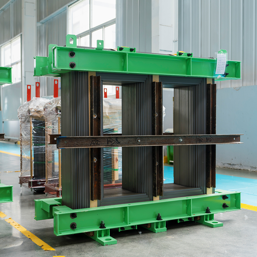
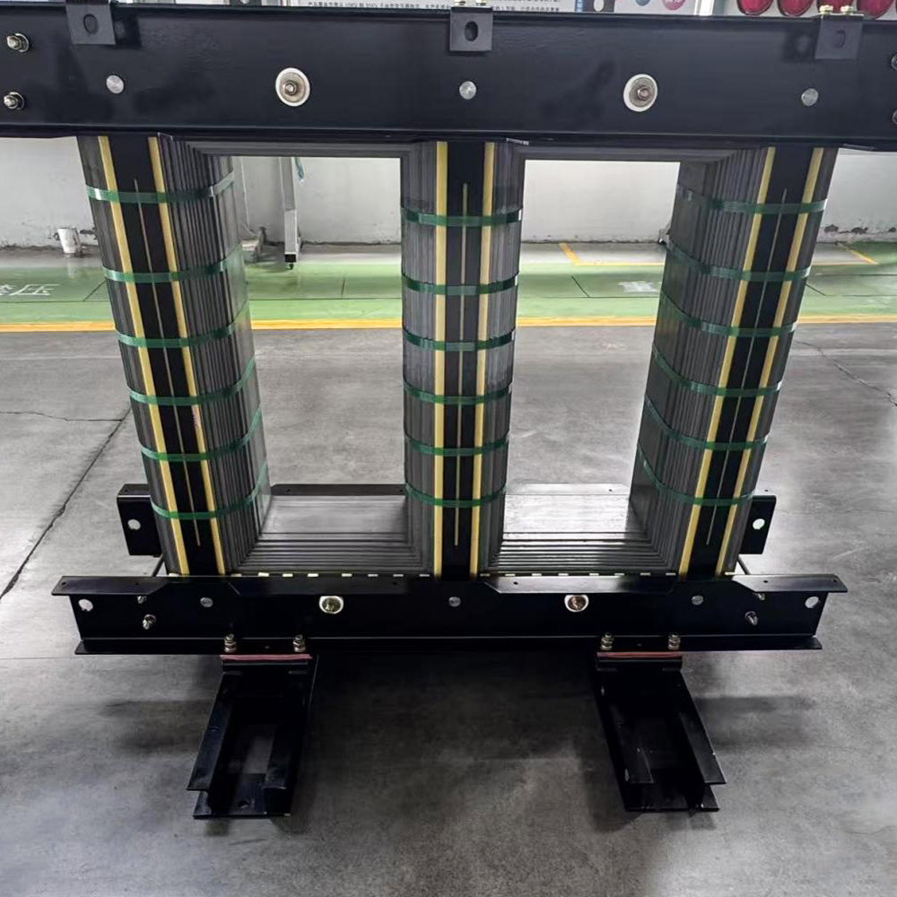 Oil-Immersed Transformer Core for Distribution TransformersBuilt from high-permeability grain-oriented silicon steel with precision shearing and stacking, this core offers low no-load loss and controlled internal stress, helping maintain uniform temperatures in oil-immersed units.View Product →
Operators should inspect cooling fans, pumps, and radiators on a regular schedule, monitor oil temperature, and verify that the cooling control system switches correctly. A rising no-load temperature trend, even under constant load, is a strong indicator of core-related thermal problems.
Preventing Thermal Breakdown Through Manufacturing Quality
The most effective way to prevent core hotspots is to build the core correctly in the first place. Three elements of manufacturing quality make the greatest difference.
Magnetic Material Selection
High-permeability grain-oriented silicon steel with thin gauge and a high-quality insulation coating reduces both hysteresis and eddy-current losses. Better material grades reduce flux distortion and lower the thermal stress on the core.
Precision Cutting and Stacking
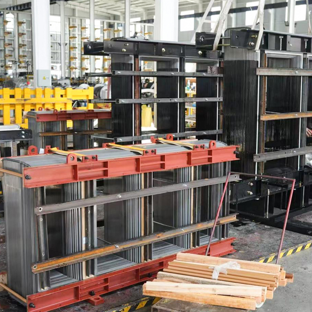
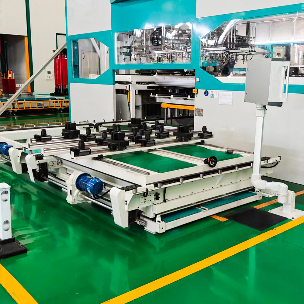
Burr-free shearing, careful handling, and controlled stacking pressure protect the interlaminar insulation. Automated production lines deliver repeatable quality that is difficult to achieve with manual assembly. A manufacturer with dedicated core production expertise can help specify the right core design for a given application. On our about page, you can see how Jiangsu Jingtianxia Electric Technology combines precision stacking equipment and transformer core manufacturing under one roof.
Advanced Core Geometry
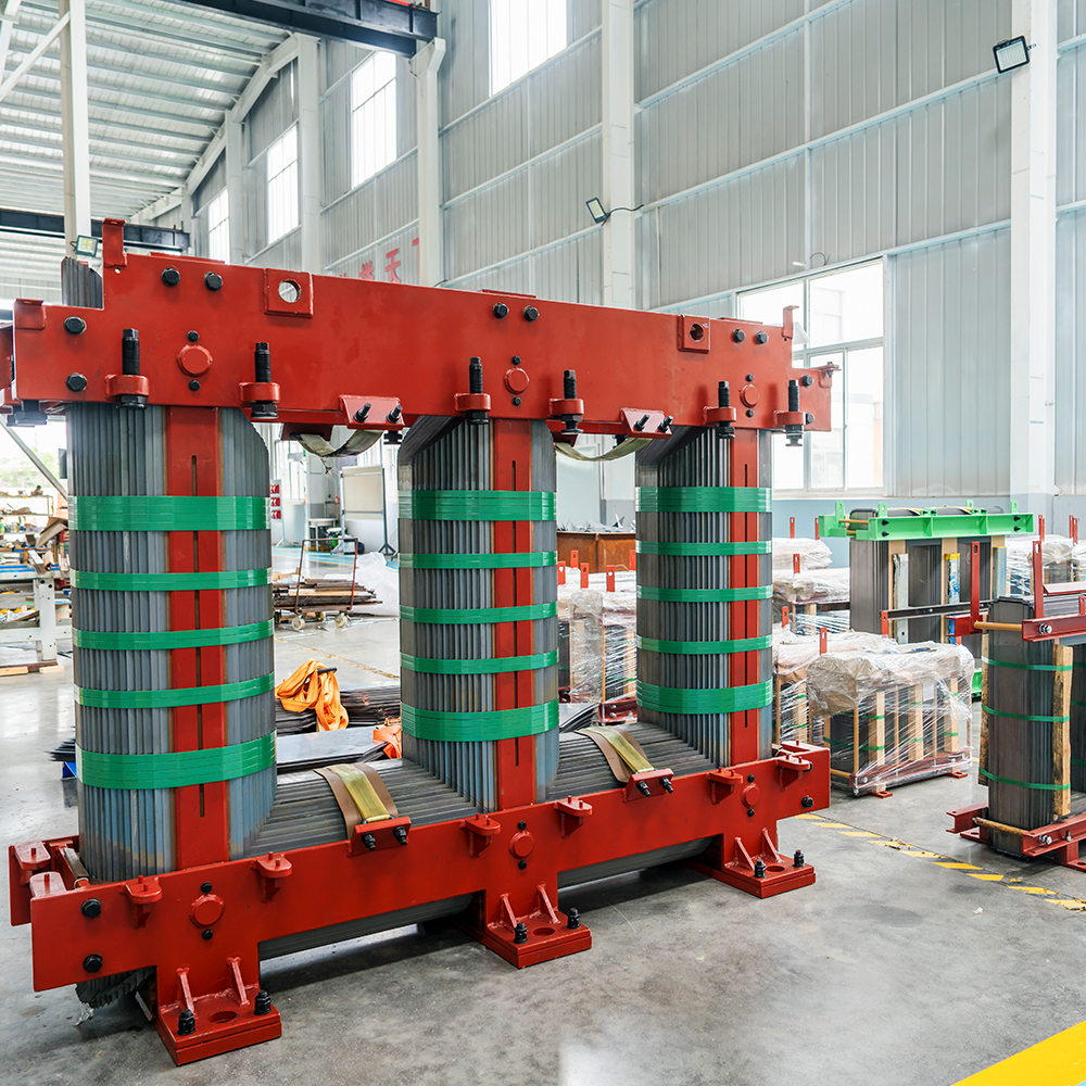
Three-dimensional triangular wound cores assemble wound silicon steel strips into a compact triangular configuration. The design shortens the magnetic path, reduces joint losses, and lowers the core temperature compared with conventional stacked cores.
 Three-Dimensional Triangular Wound Transformer CoreThis jointless wound core shortens the magnetic path and reduces losses and noise. Its symmetrical triangular design lowers core temperature compared to conventional stacked cores, making it a strong option for energy-efficient transformers.View Product →
Operation and Maintenance Practices to Prevent Thermal Breakdown
No matter how well the core is designed, sustained misoperation can still create hotspots. A practical prevention program combines load management, monitoring, and periodic inspection. Key practices include:
- Monitor load and harmonics. Avoid sustained overloading and use harmonic filters where needed.
- Track core ground current. Measure the core ground strap current during routine maintenance; a rising trend indicates a developing ground fault.
- Perform dissolved gas analysis. DGA of insulating oil reveals thermal faults early; watch for hydrogen, methane, ethylene, and carbon oxides.
- Use temperature monitoring. Winding temperature indicators and fiber-optic sensors detect abnormal trends; infrared thermography can locate surface-level hotspots.
- Keep the cooling system healthy. Check pumps, fans, radiators, and oil condition at scheduled intervals.
Many utilities lack the in-house resources to perform all of these checks regularly. Working with a professional service team ensures that core testing, oil sampling, and temperature assessments follow recognized standards and are interpreted correctly.
Frequently Asked Questions
Q1: What is the most common cause of hotspots in transformer cores?
Core overexcitation and interlaminar insulation failure are the most frequently identified causes. Overexcitation raises flux density and core loss, while damaged interlaminar insulation allows circulating currents to flow between laminations. Both produce localized heating and should be checked when a hotspot is suspected.
Q2: How can I detect a hotspot before it causes thermal breakdown?
Dissolved gas analysis is the most reliable early-warning method because thermal faults generate characteristic hydrocarbon gases. Core ground current measurement, fiber-optic temperature sensing, and infrared thermography provide additional data on the location and severity of the heating.
Q3: Can automated core stacking reduce the risk of hotspots?
Yes. Automated stacking ensures uniform clamping pressure, precise alignment, and minimal surface damage to the interlaminar coating. These three factors directly reduce the risk of circulating currents and flux-distortion hotspots.
Q4: What temperature rise is acceptable for a large transformer core?
The acceptable rise depends on the transformer design, insulation class, and loading profile. In general, the top-oil temperature and winding hot-spot temperature should remain within the limits specified in the manufacturer's test report and in standards such as IEC 60076 and IEEE C57.12.00.
Conclusion
Hotspots in large transformer cores are not random events. They are the result of identifiable physical mechanisms: overexcitation, interlaminar insulation damage, ground faults, harmonic currents, DC bias, and cooling limitations. Each mechanism leaves a thermal signature that can be detected with the right monitoring program. Combined with high manufacturing quality, from silicon steel selection to automated precision stacking, these detection methods form a complete defense against thermal breakdown.
For operators and asset managers, the message is clear: understand the causes, monitor the core, and maintain the cooling system. Taking these steps will extend transformer life, reduce the risk of unplanned outages, and keep large power transformers operating safely under increasingly demanding conditions.

-
Mobile
+86-18351152766
-
E-mail
479279940@qq.com
-
Address
No.3 Park, Jiangcun Village, Liangxu Town, Jiangyan District, Taizhou City, Jiangsu Province, China


Copyright © Jiangsu Jingtianxia Electric Technology Co., Ltd. Rights Reserved.Specializing In Transformer Core Manufacturing
