 English
 Español
 عربى
 Türk



Oil-Immersed vs. Dry-Type Transformer Cores: Design, Insulation, Cooling
Content
Choosing between an oil-immersed transformer and a dry-type transformer usually begins with the cooling medium: mineral oil versus air. Yet the deeper engineering story is written in the transformer core. The magnetic circuit, insulation system, and cooling channels are tightly interconnected, so a core-stage decision propagates through every later specification. For utilities, contractors, and plant engineers, understanding these relationships is essential.
At Jiangsu Jingtianxia Electric Technology Co., Ltd., we manufacture both dry-type and oil-immersed transformer cores, as well as the precision equipment used to build them. Drawing on that hands-on experience, this guide examines the design differences, insulation strategies, and cooling-channel layouts that separate the two core families. You can read more about our engineering and manufacturing background before diving into the technical comparison.
Core Construction and Material Design
Both core types start from the same raw-material family: grain-oriented electrical steel. Silicon steel laminations, typically 0.23 to 0.35 mm thick, are cut, stacked, and clamped to form a low-loss magnetic path. After that step, the constructions diverge sharply because the surrounding medium changes the rules for clearance, clamping, and ventilation.
Open Construction in Dry-Type Cores
A dry-type transformer core is not hermetically sealed. Because the core and windings are exposed to air or cast resin, moisture, dust, and contaminants can reach the core surface. The lamination coating must therefore be mechanically robust, and designers must respect generous creepage and clearance distances between the core, the clamping structure, and live parts. Because air is a poor coolant, dry-type designs often integrate vertical air ducts between winding layers to promote natural convection.
Sealed Tank Construction in Oil-Immersed Cores
In an oil-immersed transformer, the core sits inside a sealed tank filled with insulating oil. The oil performs three duties: it insulates, it cools, and it shields the core from oxygen and moisture. Because the dielectric strength of oil is much higher than that of air, clearances can be more compact. However, the core must include oil-flow channels, such as axial ducts and radial spacer gaps, that allow heated oil to rise toward radiators.
Core Geometry and Joint Design
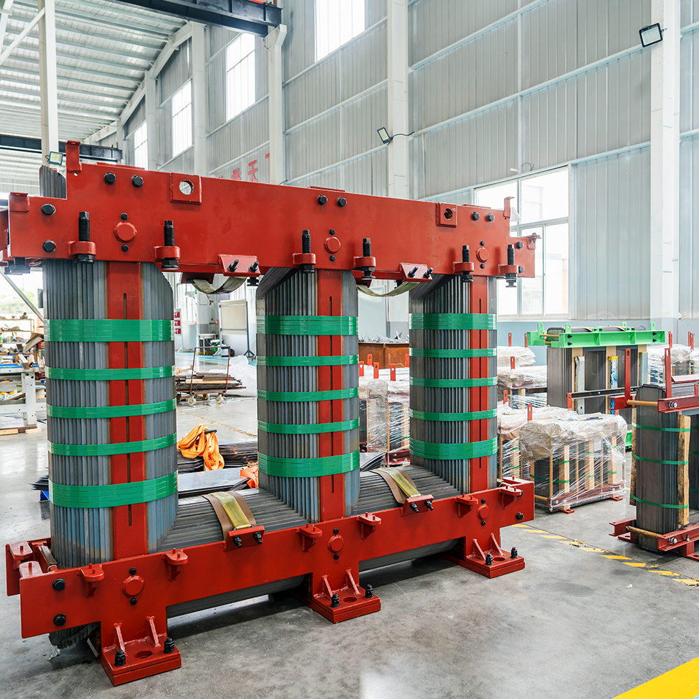
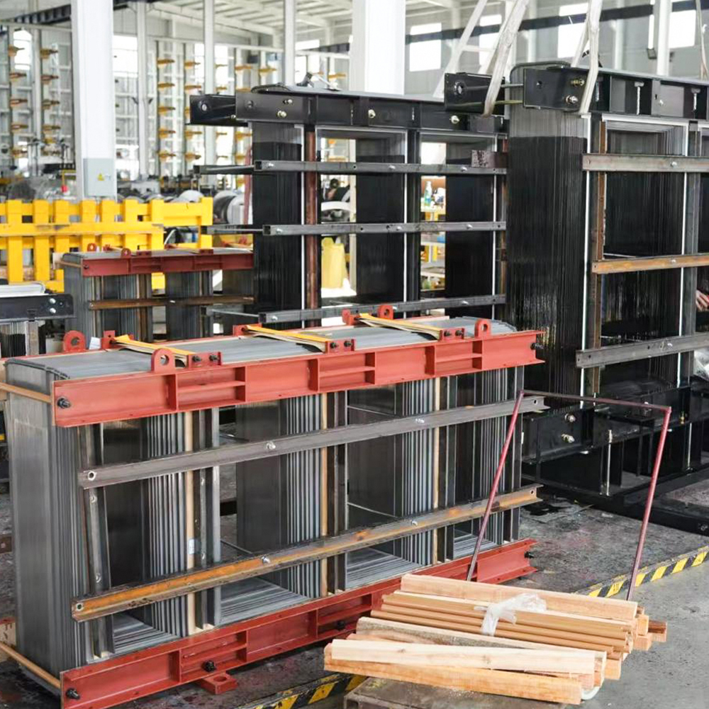
Mitered step-lap joints are common in both families because they reduce no-load losses and magnetizing current. Oil-immersed designs often use larger cross-sections because oil cooling allows higher flux density without hot spots. Dry-type cores, especially cast-resin versions, often use three-phase three-limb or five-limb layouts with deliberate ventilation gaps. A newer option is the wound-core configuration, such as a three-dimensional triangular wound core, which lowers joint losses by eliminating conventional joints.
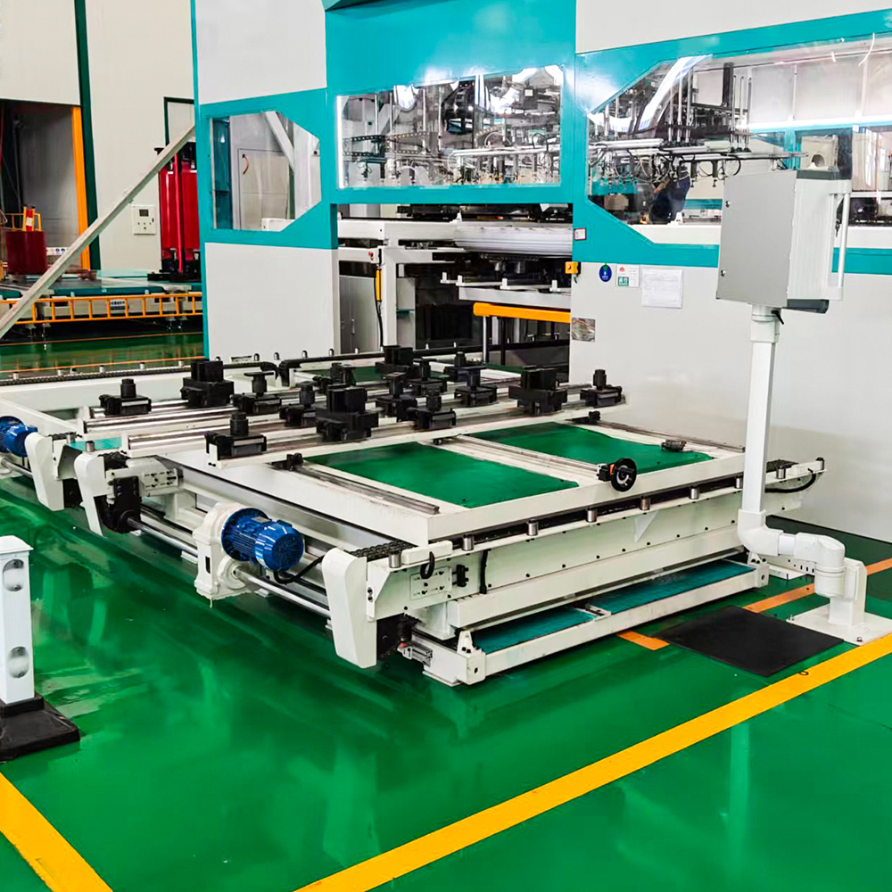
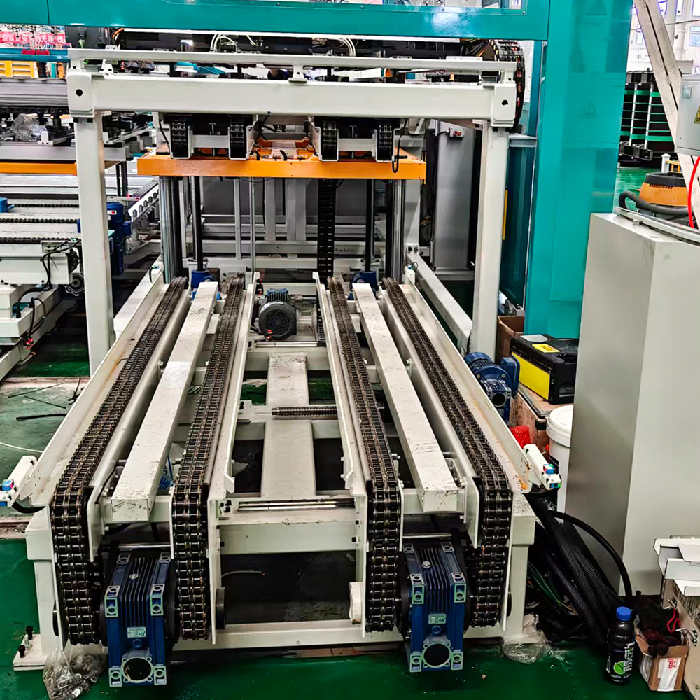
Core quality is ultimately decided in the stacking and clamping process. Mismatched laminations create air gaps that increase core loss, raise noise, and degrade efficiency. Automated stacking uses servo-controlled manipulators to position every sheet precisely, the level of control required for modern low-loss cores.
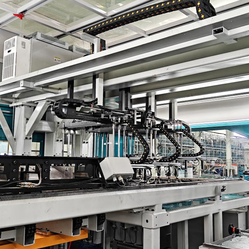 ZXD-440 Automatic In-line Transformer Core Stacking Production LineThis automated line integrates shearing and stacking in one continuous process, eliminating manual handling and improving lamination precision for low-loss cores. It directly addresses the stacking quality concerns raised in the preceding discussion.View Product →
Insulation Systems and How They Shape Core Design
Insulation is the most visible technical difference between the two technologies, and it shapes the core in subtle ways. In a transformer core, insulation must separate the grounded core and clamps from the windings while surviving the thermal and mechanical stress of decades of service.
Dry-Type Insulation: Air and Solid Resin
Dry-type transformers rely on air, epoxy resin, or cast resin as the dielectric medium. The core is separated from the low-voltage winding by aramid paper, resin-impregnated barriers, or a cast-resin cylinder. Because the dielectric strength of air is limited, isolation distances between the core, clamps, and windings must be larger, forcing a more open layout. The core itself remains the reference ground point for the whole assembly.
Oil-Insulated Cores: Paper and Pressboard
In oil-immersed units, the insulation system is cellulose-based: kraft paper, pressboard, angle rings, and transformer oil form a composite dielectric. The core is separated from the low-voltage winding by pressboard cylinders and spacers, and the entire assembly is vacuum-dried and impregnated with degassed oil before sealing. The higher dielectric strength of oil allows a more compact core-to-winding distance, which reduces leakage flux and eddy-current losses in clamps.
Insulation Classes and Temperature Limits
Class F and Class H insulation are standard for dry-type cores, permitting operating temperatures of 155°C and 180°C respectively. Oil-immersed transformers are limited by paper degradation, normally to a 65°C average winding temperature rise over a 40°C ambient. That difference changes how aggressively the core can be loaded and directly influences the economics of each design.
For indoor installations that demand fire-safe and low-maintenance construction, we supply dry-type transformer cores engineered for Class H insulation and natural-air cooling.
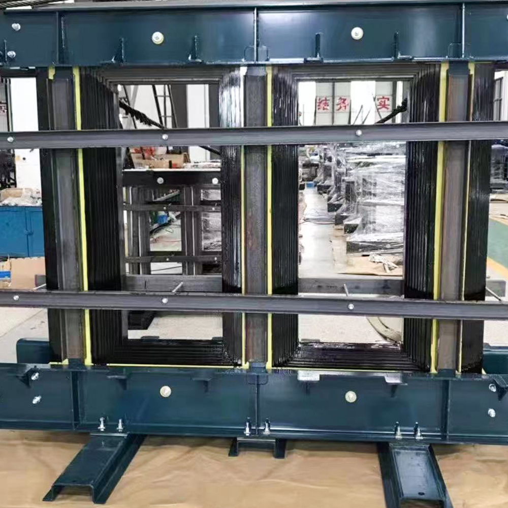 Dry-Type Transformer Core for Resin Cast ApplicationsBuilt with grain-oriented silicon steel and step-lap stacking, this core keeps noise below 55 dB and meets low-loss standards. It suits SCB10–SCB13 dry-type transformers for noise-sensitive indoor installations, as highlighted in the surrounding text.View Product →
Cooling Channels and Thermal Management
Cooling channels are where the design differences turn into measurable thermal performance. A core can become the hottest part of the assembly if cooling paths are not planned with the magnetic circuit.
Oil Circulation Paths in Core and Windings
Oil-immersed cores use channels that let oil flow axially between the limbs and radially through spacer blocks along the winding height. Under ONAN operation, the oil circulates by convection: heated oil rises through the core ducts, releases heat in radiators or cooling tubes, and returns to the bottom of the tank. Adding forced-air (ONAF) or forced-oil (OFAF) stages multiplies capacity but requires the channel geometry to be designed for directed oil flow from the start.
Air-Flow Paths in Dry-Type Cores
Dry-type cores depend on natural or forced air convection. The core and windings are assembled with vertical air ducts, and the transformer housing is ventilated at the bottom and top to create a chimney effect. In higher-rated units, fans push air through the same channels. Because air has far lower heat capacity than oil, dry-type cores are designed with a larger thermal margin and a lower operating flux density.
Hot-Spot Control and Thermal Ageing
Hot spots accelerate insulation ageing and increase core loss. In oil-immersed cores, hot-spot temperature is controlled by duct layout and oil-flow direction. In dry-type cores, it is controlled by duct size, resin surface area, and cooling air passes. In both cases, designers balance flux density, channel width, and mechanical stiffness to keep hot spots below the rated limit.
For utility and substation duty where high continuous capacity is required, our oil-immersed transformer cores are built with optimized duct layouts for ONAN and ONAF operation.
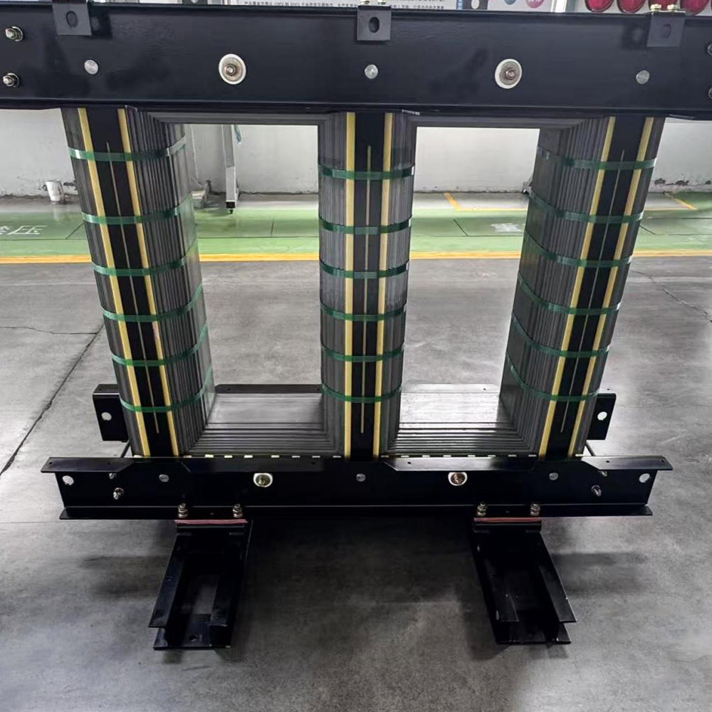 Oil-Immersed Transformer Core for Distribution TransformersDesigned for S11 and S13 oil-immersed transformers, this core uses high-permeability silicon steel and precision stacking to achieve ultra-low losses and stable no-load current. It supports ONAN/ONAF operation, matching the utility-duty context described.View Product →
Side-by-Side Comparison of Core Characteristics
The table below summarizes the most important differences between dry-type and oil-immersed transformer cores.
| Parameter | Dry-Type Core | Oil-Immersed Core |
|---|---|---|
| Insulation medium | Air, epoxy resin, cast resin | Mineral oil, paper, pressboard |
| Core enclosure | Open or ventilated housing | Sealed oil-filled tank |
| Cooling channels | Vertical air ducts and fans | Axial and radial oil ducts, radiators |
| Temperature class | Class F or Class H | Class A, paper limited |
| Core-to-winding distance | Large clearance required | Compact distance possible |
| Maintenance demand | Low, periodic cleaning | Oil sampling and leak checks |
| Fire risk | Low, self-extinguishing | Higher, requires containment |
| Typical application | Indoor, commercial, offshore | Substation, utility, outdoor |
Application-Driven Selection Guidance
The choice is ultimately dictated by the installation environment, load profile, and acceptable failure mode. Both technologies can be engineered to high efficiency; the differentiator is the operating context.
- Indoor and fire-sensitive buildings: dry-type cores eliminate the risk of oil leakage and drastically reduce the fire load, making them ideal for high-rise buildings, hospitals, data centers, and commercial complexes.
- Outdoor substations and utility grids: oil-immersed cores deliver higher power density and proven long-term service behavior, which favors them for distribution stations, transmission substations, and industrial yards where oil containment can be arranged.
- Continuous high-load duty: oil cooling removes heat more effectively, so oil-immersed cores can sustain higher average load factors without exceeding temperature limits.
- Intermittent and variable loads: dry-type cores handle cycling loads well and respond quickly because there is no large oil volume to heat or cool.
- Confirm the installation location: indoor, outdoor, or confined space.
- Check local fire codes and oil containment regulations.
- Define the continuous and cyclic load profile.
- Evaluate altitude and ambient temperature derating for both core types.
- Compare the total cost of ownership, including maintenance and losses.
Beyond the core itself, the manufacturing route determines long-term reliability. A core built with precise stacking, controlled clamping pressure, and verified joint gaps will serve either type faithfully. Our transformer core range covers both configurations, and our engineers can tailor the lamination scheme, duct layout, and clamping structure to your specification. You can review the full transformer core range for more detail.
Frequently Asked Questions
Q1: Can the same silicon steel grade be used for both core types?
Yes. Grain-oriented steel grades such as 30Q130 or 27Q120 are commonly used in both dry-type and oil-immersed cores. What changes is the lamination coating, the cutting quality, the stacking pattern, and the way cooling channels are integrated around the core.
Q2: Why is a dry-type core often heavier for the same rating?
Because air cooling is less effective than oil cooling, dry-type cores must run at a lower flux density and therefore use more lamination material to keep losses and temperature within limits. In addition, cast-resin encapsulation adds considerable weight.
Q3: Do cooling channels affect transformer efficiency?
Yes. Poorly placed ducts can obstruct the magnetic circuit or create stray losses. Well-designed channels remove heat without enlarging the core frame, keeping no-load losses steady and reducing hot-spot risk.
Q4: Which core type is more fire-safe?
Dry-type cores with resin insulation are practically self-extinguishing and are therefore preferred indoors. Oil-immersed cores contain a flammable liquid and require fire barriers, containment pits, or safe separation distances when installed close to structures.
Conclusion
Dry-type and oil-immersed transformer cores serve different operating priorities and installation environments. Dry-type cores trade some material efficiency for safety, simplicity, and indoor convenience. Oil-immersed cores exploit the excellent dielectric and heat-transfer properties of oil to deliver compact, high-capacity designs for utility-scale duty. The right choice depends on where the transformer will live, how it will be loaded, and which risks the owner can manage.
Whichever direction you choose, the core should be built with tight stacking tolerances, verified joint geometry, and a cooling-channel layout matched to the rated duty. When those fundamentals are respected, both core types deliver the efficiency and service life demanded by modern power equipment.

-
Mobile
+86-18351152766
-
E-mail
479279940@qq.com
-
Address
No.3 Park, Jiangcun Village, Liangxu Town, Jiangyan District, Taizhou City, Jiangsu Province, China


Copyright © Jiangsu Jingtianxia Electric Technology Co., Ltd. Rights Reserved.Specializing In Transformer Core Manufacturing
